
Custom Sheet Metal Brackets for Your Assembly
ShincoMetal is a China-based sheet metal manufacturer for custom mounting, support, and connecting brackets. Send your finished-part drawing and CAD model to discuss a bracket built around your mounting interfaces, available space, and assembly requirements.
Start with the features that control fit: mounting holes, formed heights, offsets, contact surfaces, and access for installation. Identify these requirements in your drawing so they can be considered together with material, forming, and finishing.
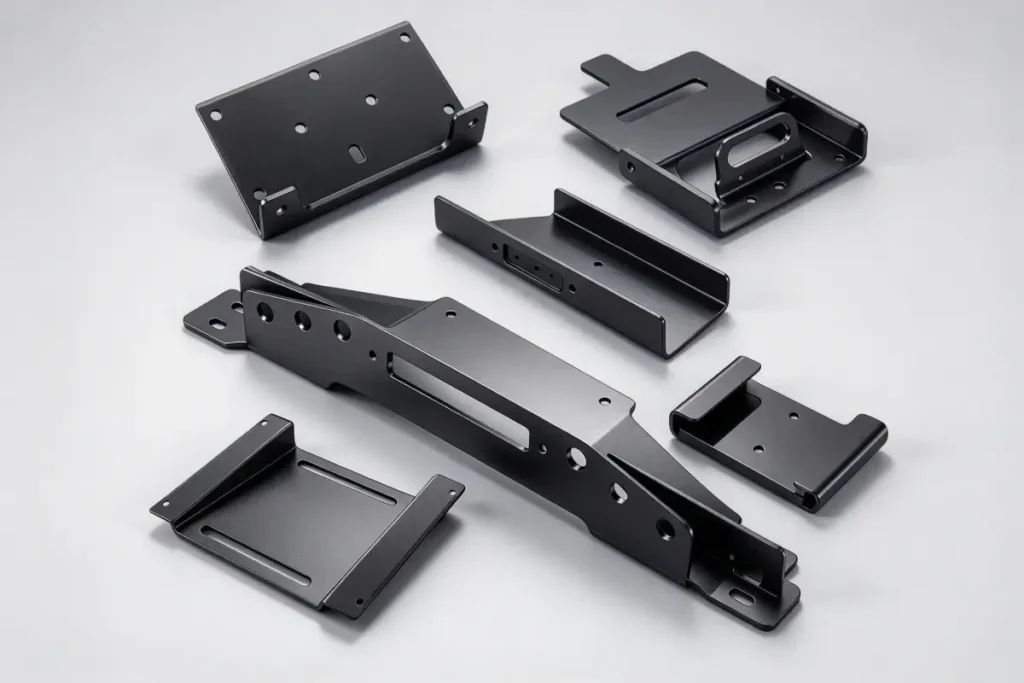
Check Your Bracket Against Our Manufacturing Scope
Send the finished-part drawing together with the material, thickness, quantity, and critical mounting requirements. Use the ranges below for an initial discussion; feasibility also depends on bend geometry, tool access, hardware, and the condition of the finished part.
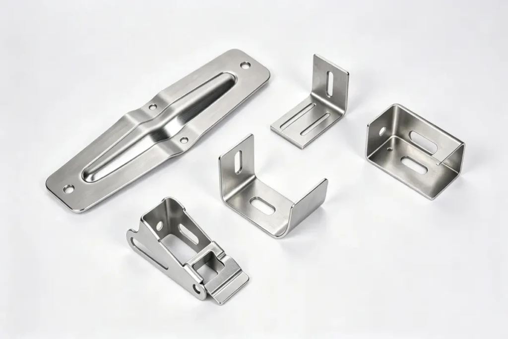
| Requirement | Scope for Initial Review | Conditions to Include |
|---|---|---|
| Steel brackets | Cold rolled and galvanized steel, with a proposed thickness range of 0.8–6.0 mm | Material grade, corrosion exposure, bend geometry, and finish requirements. |
| Stainless steel brackets | 304 and 316 stainless steel, with a proposed thickness range of 0.8–4.0 mm | Grade, surface requirements, inside bend radius, and any welded joints. |
| Aluminum brackets | 5052 aluminum, with a proposed thickness range of 1.0–6.0 mm. Selected 6061 grades and tempers may also be reviewed | Temper, grain direction where relevant, bend radius, and finished-part stiffness. |
| Part size and forming access | Submit the flat blank dimensions and finished-part envelope for review. Cutting feasibility and forming feasibility must be assessed separately, taking material, thickness, bend sequence, and tooling access into account. | Overall length, width, and height; inside channel width and depth; shortest flange; return bends; and any mating geometry that limits installation clearance. |
| Formed geometry | L, Z, U/channel, top hat, and reinforced bracket configurations are available for drawing review | Inside dimensions, offsets, closely spaced bends, and installation access. |
| Critical interfaces | Identify mounting-hole relationships, formed heights, offsets, and mating surfaces. Acceptance of specified tolerances is subject to drawing review | Finished-part datums, required tolerances, mating geometry, and whether acceptance applies before or after finishing. |
| Secondary operations | Welding and installation of compatible captive nuts, studs, or standoffs | Joint specifications, hardware part numbers, sheet compatibility, and installation clearance. |
| Surface treatment | Powder coating, zinc plating, aluminum anodizing, and stainless steel passivation, as applicable to the substrate | Finish specification, masking, thread protection, and dimensional requirements after treatment. |
Do not see your material or size listed? Include it in your inquiry for review. For deep channels, short flanges, or hole patterns spanning several bends, provide the formed model and identify the interfaces that must fit together.
Bracket Shapes for Different Mounting Requirements
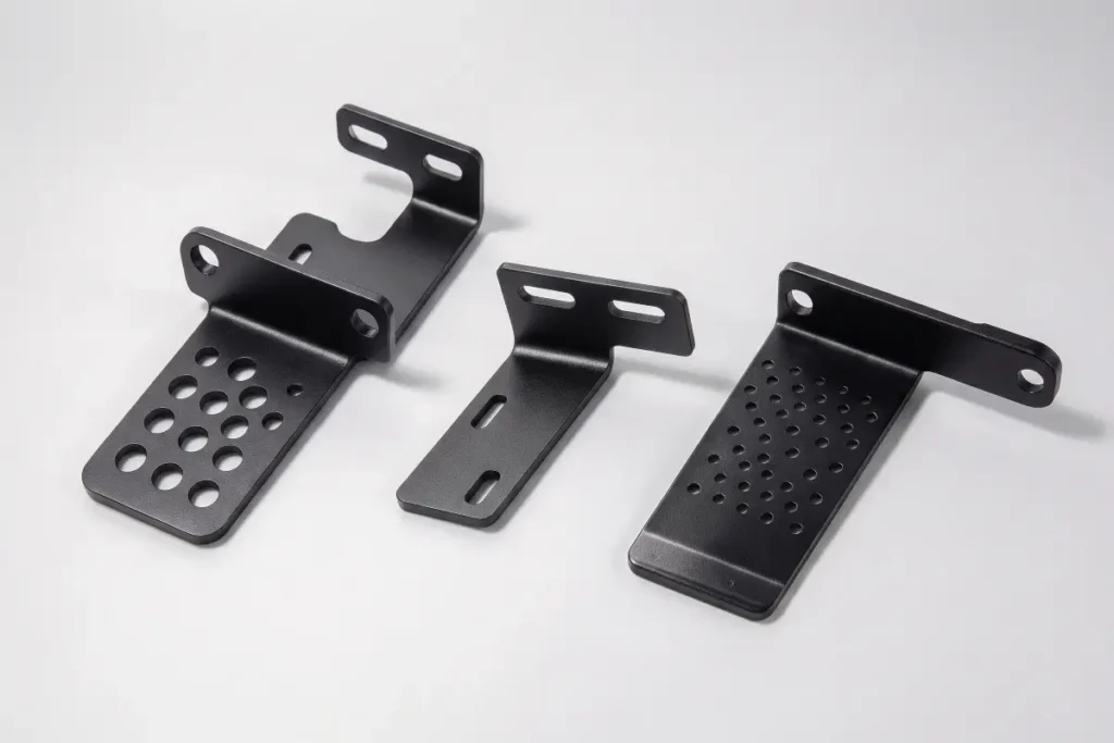
The starting shape should follow the load path, installation space, and fastener access. Similar-looking brackets can require different manufacturing approaches when their dimensions or mounting conditions change.
| Bracket type | Typical purpose | Features to define |
|---|---|---|
| L bracket | Connect perpendicular mounting faces | Leg lengths, bend angle, hole locations, and fastener access |
| Z bracket | Connect parallel faces at different heights | Offset height, mounting-plane relationship, and hole position across bends |
| U or channel bracket | Locate or support a component between opposing flanges | Inside width, flange parallelism, and installation clearance |
| Top hat bracket | Raise a mounting surface above a base | Bridge height, return-flange geometry, and clearance beneath the bracket |
| Gusseted or ribbed bracket | Increase stiffness where the assembly permits reinforcement | Load direction, reinforcement position, joint requirements, and access |
| Multi-part bracket assembly | Combine mounting features that are difficult to form in one piece | Joint locations, accumulated variation, hardware, and assembly sequence |
A longer unsupported leg may deflect even when the material does not yield. Adding thickness is one option; changing the section, shortening the span, or revising the fastener pattern may be more effective for the assembly.
Define the Dimensions That Control Assembly Fit
A useful drawing distinguishes functional interfaces from noncritical edges. A hole pattern that locates a component may need tighter control than an outside profile that only provides clearance.
Achievable tolerances depend on the material, thickness, feature geometry, manufacturing sequence, and inspection method. State the required tolerance on the finished-part drawing rather than relying on a general expectation of precision.
| Critical feature | What affects the result | What to specify |
|---|---|---|
| Mounting holes and cut profile | Hole size, edge distance, thickness, and cutting method | Hole dimensions, location datums, and mating requirements |
| Bend angle and inside radius | Alloy, temper, grain direction, tooling, and springback | Required angle, radius where functional, and acceptance condition |
| Hole position across bends | Bend allowance and accumulated forming variation | Finished hole relationship and the datums used to inspect it |
| Formed height and offset | Bend sequence, tool access, and datum selection | Functional height or offset and its mating surface |
| Joined features | Joint layout, restraint, access, and heat input | Joint requirements and dimensions after joining |
| Coated or treated surfaces | Treatment thickness, masking, and contact requirements | Whether dimensions apply before or after finishing |
For a hole pattern spanning several mounting planes, include the mating geometry or an assembly reference where available. This helps explain which relationships must be preserved and where normal process variation can be accommodated.
Holes, Reliefs, and Short Flanges
Holes near a bend can distort or shift as the surrounding material forms. The relevant clearance depends on thickness, bend radius, opening geometry, and tooling.
Bend relief can prevent tearing or interference at a terminating bend. Short flanges also need enough support for the selected forming method. Neither issue is reliably resolved by a single rule based on thickness alone.
Hardware and Tool Access
Self-clinching hardware requires compatible sheet thickness, hardness, edge distance, and installation conditions. The insertion tooling needs clearance before assembly, and the installed bracket needs access for screws, drivers, or wrenches.
Check both manufacturing access and service access. A bracket can be straightforward to fabricate yet difficult to install.
Choose Material for the Environment and Load Conditions
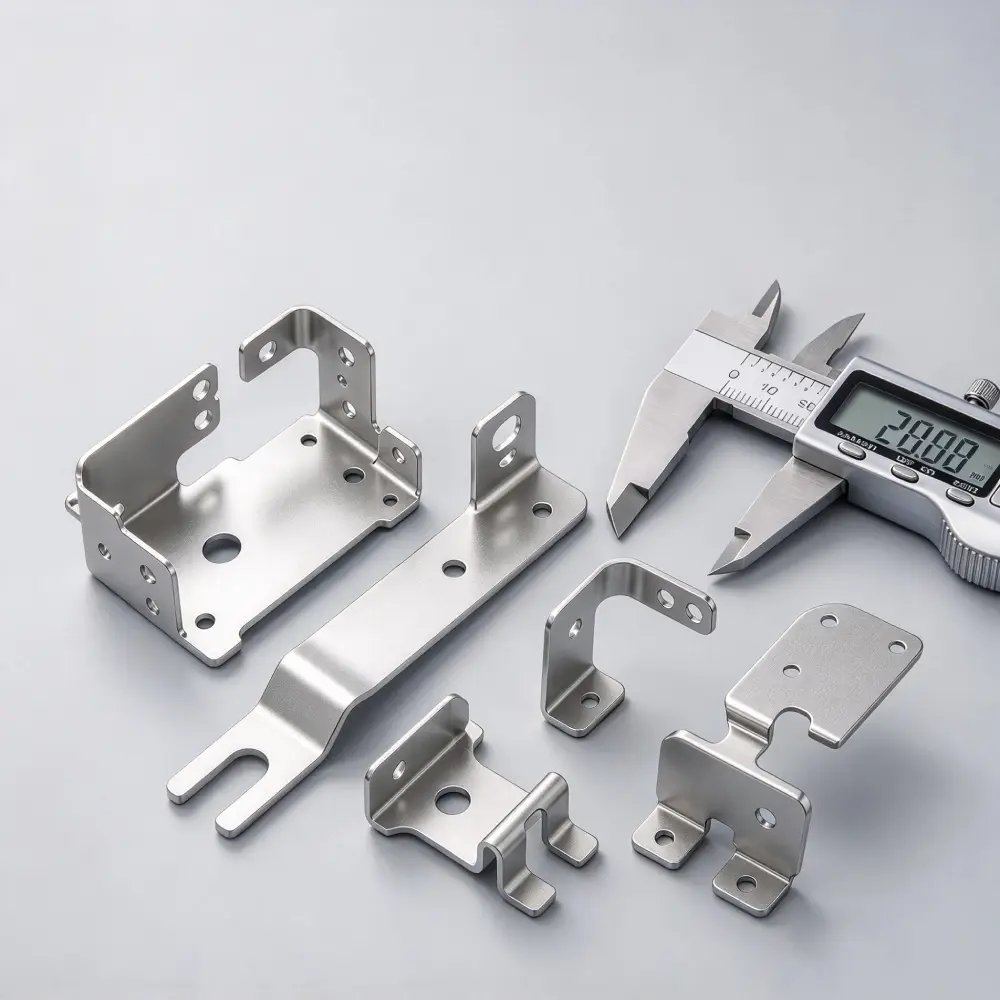
Material selection balances stiffness, mass, formability, corrosion exposure, and finish requirements. The comparisons below explain design considerations; availability for your part must be confirmed during quotation.
| Material family | Reasons to consider it | Conditions to review |
|---|---|---|
| Cold rolled steel | General equipment brackets where stiffness and strength are priorities | Corrosion protection, cut edges, coating damage, and finished weight |
| 304 stainless steel | Many indoor and washdown environments | Cleaning chemistry, crevices, surface condition, and exposure |
| 316 stainless steel | Improved resistance to chloride attack compared with 304 in many conditions | Actual chloride exposure, temperature, cleaning regime, and geometry |
| 5052 aluminum | Relatively low mass and good formability | Temper, bend direction, radius, and stiffness of the finished section |
| 6061 aluminum | Strength-to-weight characteristics in suitable conditions | Temper and bend geometry; tight bends in T6 material can crack |
| Galvanized steel or galvanneal | Zinc-based protection, with galvanneal often selected for painting | Forming damage, cut edges, welding, and coating preparation |
Thickness alone does not establish load capacity. Span, load direction, fasteners, support conditions, and fatigue exposure all affect performance.
For safety-critical or dynamically loaded assemblies, define the required engineering validation separately from dimensional inspection.
Specify Hardware, Joints, and Finish Together
Secondary operations can change fit and installation behavior. Include them in the finished-part specification rather than treating them as cosmetic additions.
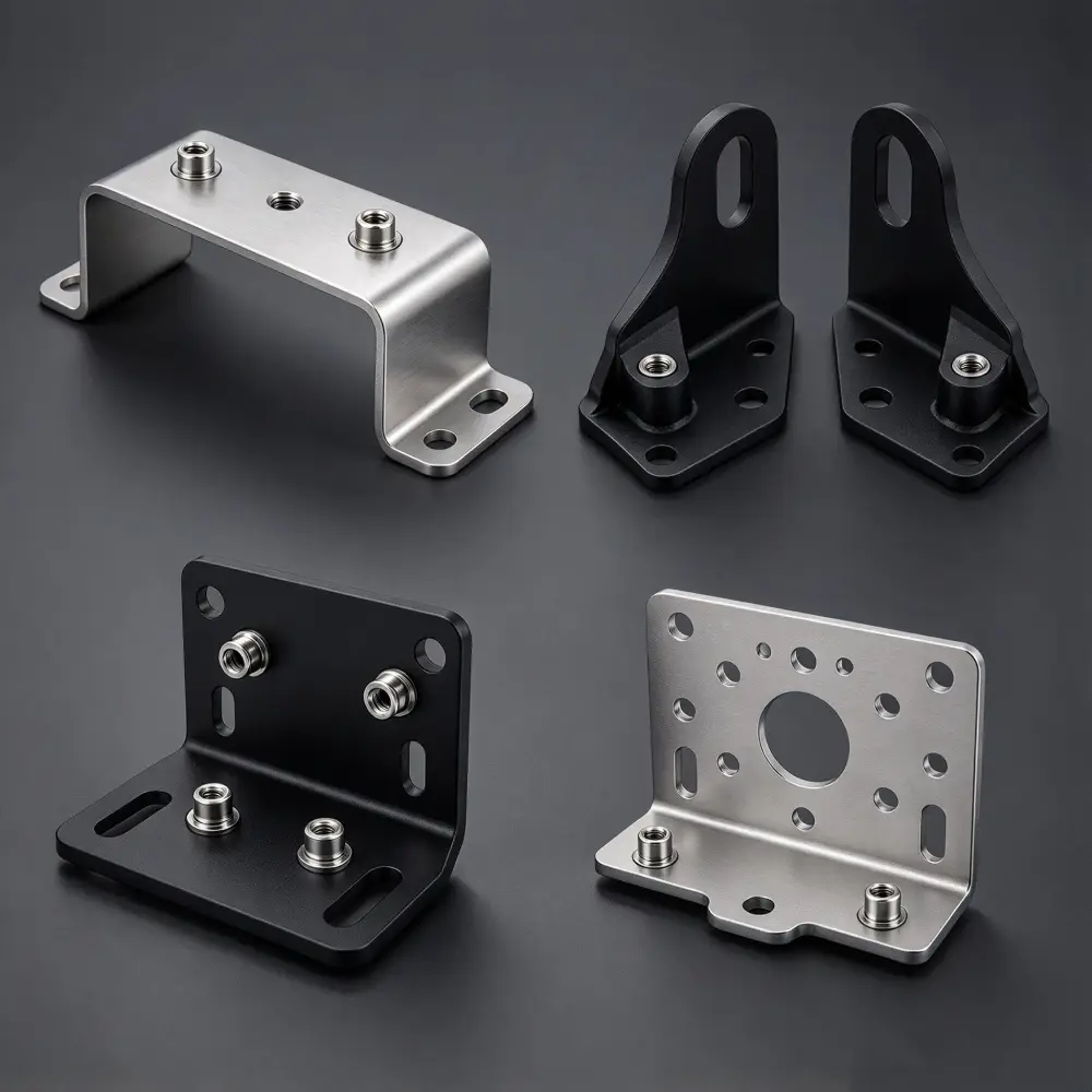
Captive Hardware
Nuts, studs, and standoffs can reduce loose hardware during assembly. Specify the hardware type and location, together with any thread protection, electrical contact, or installation requirements.
Coating buildup on threads or seating faces can interfere with assembly. Identify surfaces that require masking or a defined post-finish condition.
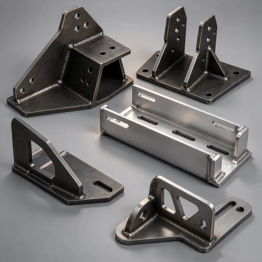
Welded Connections
Joint geometry affects welding access and distortion. Spot welding typically requires overlapping sheet and electrode access. TIG or MIG suitability depends on the material, joint requirements, and production conditions.
Use appropriate weld symbols or an agreed joint specification. A general request for a “strong weld” does not define size, extent, appearance, or acceptance requirements.
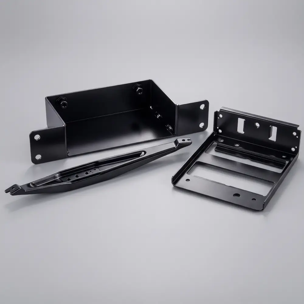
Edge and Surface Requirements
A deburred edge is different from a specified radius. Where a bracket contacts cables, hands, seals, or a mating surface, define the edge condition needed for that interface.
Powder coating, zinc plating, anodizing, and passivation apply to different materials and requirements. A finish name alone does not define thickness, color, masking, appearance, or corrosion acceptance.
From Prototype Review to Repeat Orders
Prototype and production decisions should use the same finished-part requirements, while accounting for different quantities and approval stages.
Prototype fit review
For an initial fit check, prioritize the mounting interfaces, installation access, clearances, and finish effects. Record any approved changes in the drawing revision before repeat production.
When dedicated tooling makes sense
Dedicated tooling may become economical when geometry and demand are sufficiently stable. Tool cost, maintenance, revision risk, and expected lifetime volume belong in that comparison. There is no universal quantity at which stamping becomes the best choice.
Repeat-order checklist
For recurring orders, compare quotations using consistent assumptions:
- Material grade, temper, and thickness.
- Drawing revision and finished dimensions.
- Hardware, welds, and surface treatment.
- Inspection scope and required documentation.
- Packaging, order quantity, and expected repeat demand.
Agree on Inspection Before Production
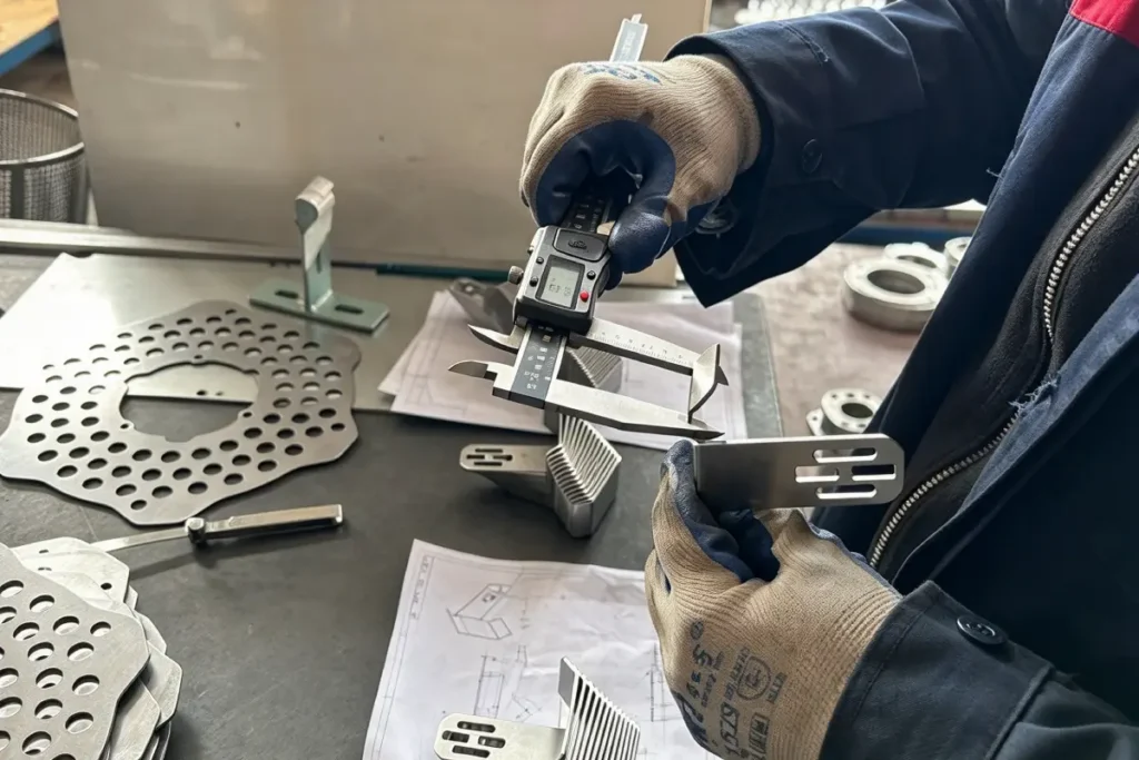
Bracket inspection should follow the interfaces that matter at installation. Checking outside dimensions alone may miss a hole relationship, mounting-plane error, or hardware problem.
The following inspection arrangement is proposed for agreement during quotation.
| Requirement | Proposed inspection approach |
|---|---|
| Hole spacing, formed height, and offset | Check designated features against the agreed drawing datums, using measurement methods suitable for the required tolerance. |
| Bend angle and mounting-plane relationship | Check relevant angles, parallelism, or perpendicularity in the specified part condition. |
| Assembly fit | Use an agreed mating fixture, representative component, or assembly check when required and available. |
| Captive hardware | Check specified type, position, seating, and thread function; additional retention tests require an agreed method and acceptance criteria. |
| Welded features | Check specified weld location, extent, and visual acceptance; additional testing must be defined for the project. |
| Edges and finish | Check agreed edge condition, masking, and appearance; coating thickness or performance tests require a defined specification and scope. |
| Documentation | Material records, first-article reports, and finish documentation may be included where agreed and available. |
A dimensional report does not establish load capacity. Material documentation does not certify the complete assembly, and a finish inspection does not establish corrosion performance unless the relevant test and acceptance criteria are defined.
Frequently Asked Questions
Can I start with a sketch or an existing bracket?
You can begin an inquiry with a dimensioned sketch or photographs explaining the part and its mounting interfaces. Mark missing information clearly. Whether additional measurement, CAD preparation, or a physical sample is needed depends on the project.
What tolerance should I specify?
Specify tolerances according to assembly function. Identify the hole relationships, mounting planes, offsets, and contact surfaces that control fit. Achievable values depend on the material, geometry, process sequence, and inspection method.
How is lead time determined?
Timing depends on material availability, geometry, quantity, finishing, tooling, and inspection scope. Include your required delivery date and any prototype approval stage so the schedule can be considered for the actual project.
What should I provide if parts fail receiving inspection?
Contact ShincoMetal with the part number, revision, affected quantity, photographs, and measured results against the agreed drawing. Include the measurement method and datum setup where relevant. Resolution should follow the agreed order terms.
Which files should accompany my RFQ?
A STEP model is useful for communicating formed geometry, while a dimensioned PDF defines tolerances, material, and finish requirements. A DXF can describe a flat profile but does not by itself define the finished bracket. State which formats you have available.
Can you manufacture a bracket to a required load rating?
Provide the loads, directions, support conditions, fasteners, and applicable validation requirements. Manufacturing to a drawing and establishing a load rating are different scopes. Do not assume that material thickness or a dimensional inspection proves structural performance.
Is there a standard minimum order quantity?
Minimum quantity and setup economics depend on the part and production route. Send the quantity you need, along with expected repeat demand, for a project-specific discussion.
Request a Quote for Your Custom Sheet Metal Brackets
Send your bracket requirements, CAD models, and finished-part drawings to ShincoMetal for a project-specific review. Please include material, quantity, finish, and critical interfaces to help us provide an accurate quotation.
Factory Address
Building 1, No.8, Second Street, Huangjiang Town,
Dongguan City, Guangdong Province
Email
contact@shincometal.com
Phone / WhatsApp
+86 13392819510
Factory Visits
Please contact us in advance to arrange a factory visit.