
Custom Sheet Metal Parts for OEM Assemblies
ShincoMetal is a China-based manufacturer of made-to-order sheet metal components. We work from your drawings and CAD files to define the fabrication requirements for brackets, panels, enclosures and other assembly parts.
Start with the features that determine whether your part will fit and function: mounting positions, formed dimensions, fastening points and finished surfaces. Include your material, quantities and acceptance requirements so the quotation addresses the complete component.
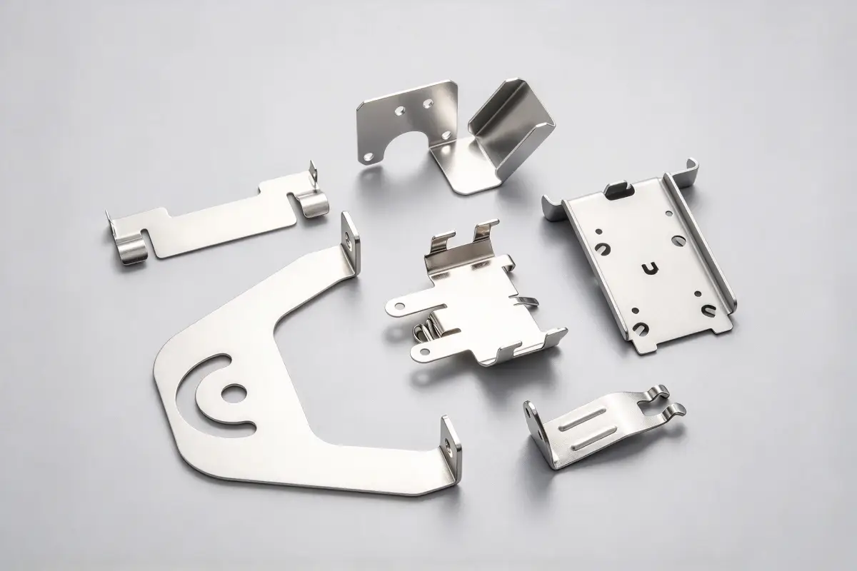
Is Your Project a Fit?
The first review connects your part requirements with the proposed manufacturing route. Material grade, thickness, overall geometry, bend access and finishing requirements all affect feasibility.
Material and Part Scope
The following ranges are initial screening information. Final suitability depends on the drawing, material condition and required operations.
| Material or requirement | Initial screening scope | Conditions for review |
|---|---|---|
| Carbon steel sheet | Thickness range: 0.8–6.0 mm | Grade, part dimensions, bend geometry and corrosion protection |
| Stainless steel sheet | Thickness range: 0.8–4.0 mm | Grade, surface condition, forming requirements and weld appearance |
| Aluminum sheet | Thickness range: 1.0–6.0 mm | Alloy, temper, bend radius and finish |
| Copper and brass | Availability and processing scope reviewed by alloy and drawing | Conductivity requirements, forming behavior and contact surfaces |
| Large or complex parts | Maximum blank and formed-part dimensions assessed against available equipment | Cutting envelope, bend length, tooling access and handling |
| Prototype and repeat orders | Prototype, pilot and production quantities quoted by project | Setup, tooling, finishing minimum charges and release quantities |
These are screening ranges, not guarantees for every combination of material, size and geometry. Parts near a process limit, closed profiles and features requiring special tooling need a drawing-specific assessment.
Manufacturing Responsibility
Laser cutting, press brake bending and hardware installation are in-house operations. Welding methods and suitable materials require confirmation against the actual equipment and production scope.
Surface finishing uses qualified external processing partners, with ShincoMetal coordinating specifications and final acceptance.
Identify any restrictions on subcontracting, approved processors or process traceability in your RFQ.
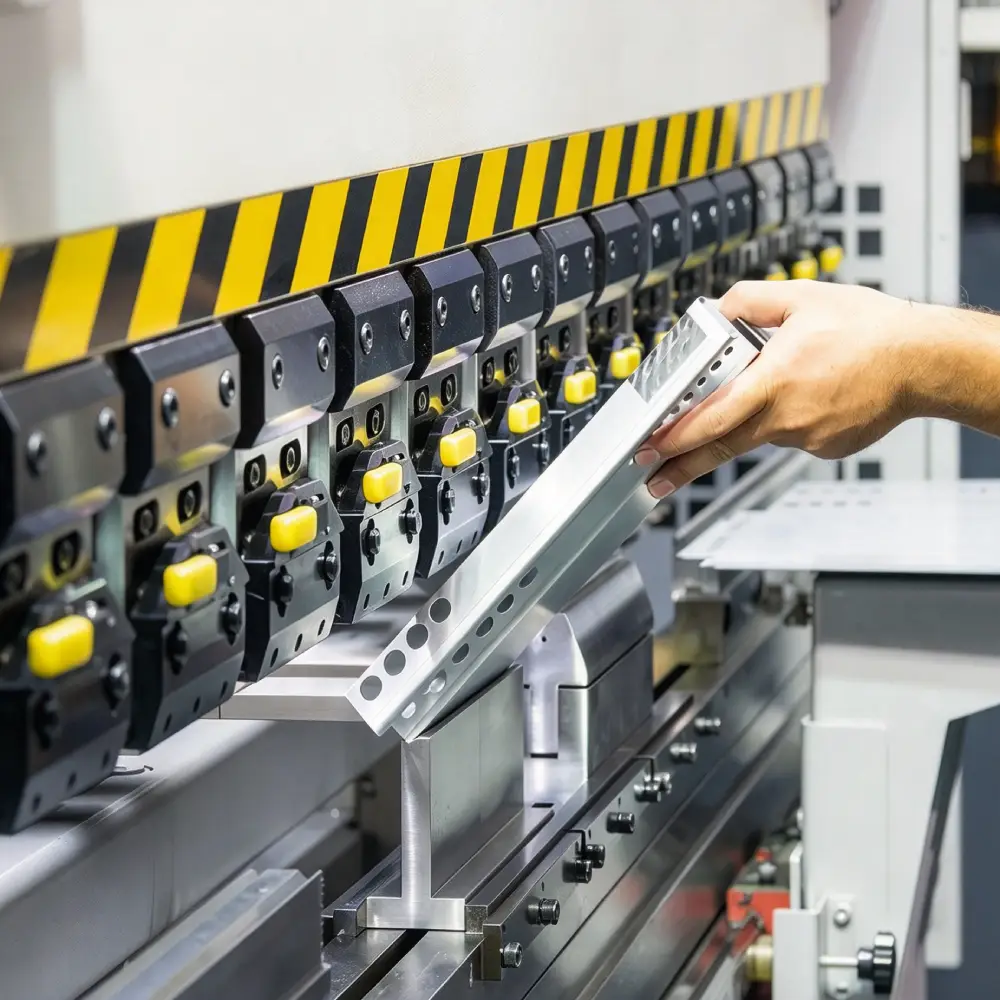
Choose the Fabrication Route Around the Part
A suitable process route must produce the required geometry while preserving access for later operations. Cutting, forming, joining, hardware installation and finishing need to work as one sequence.
Cutting and Openings
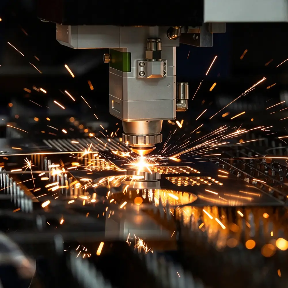
Laser cutting creates profiles, holes, slots and access openings before forming. Small holes, narrow webs and edge requirements need review alongside the overall outline.
For panels with connectors or ventilation patterns, identify which openings control component alignment and which edges need additional preparation.
Punching, louvers and embossed features require separate consideration of tooling, feature geometry and quantity. Their availability must be established before they become part of the quoted scope.
Bending and Formed Geometry
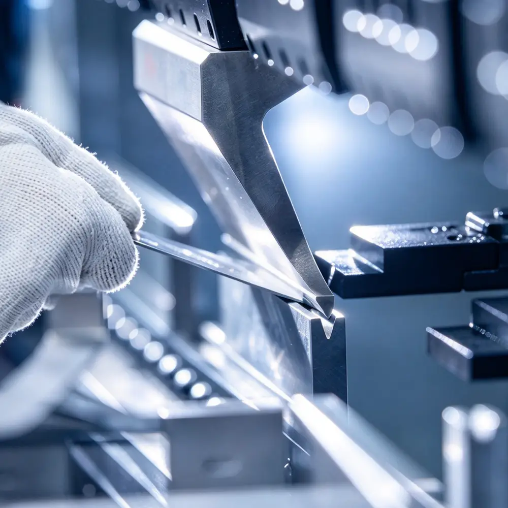
Bending creates brackets, trays, channels and enclosure sections. Flange length, inside radius, bend sequence and tool clearance affect what can be formed.
Long returns and closed shapes can restrict access. Holes near a bend may distort during forming, while accumulated bend variation can affect the finished assembly envelope.
Welding and Joining
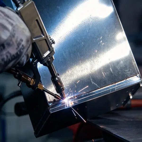
Joint design influences accessibility, distortion, strength and appearance. TIG, MIG and resistance spot welding suit different materials and joint configurations; the appropriate method depends on the actual part.
Specify whether a joint is structural, cosmetic or required to resist leakage. A continuous-looking seam alone does not establish sealing performance.
Define the Dimensions That Control Assembly
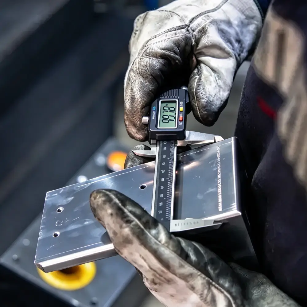
Tolerances are most useful when they describe how the part locates, fits and functions. Dimensions in one flat face need different consideration from dimensions across several bends.
Mark critical interfaces on the drawing rather than applying the same tight tolerance to every feature.
| Feature | What to define | Why it matters |
|---|---|---|
| Mounting holes | Datums, position requirements and mating features | Aligns fasteners and connected components |
| Dimensions across bends | Finished dimensions, angles and reference faces | Controls bracket spacing and enclosure fit |
| Holes near bends | Hole function and relationship to the formed area | Helps assess distortion and fastener access |
| Flat or sealing faces | Required condition and inspection basis | Supports contact, alignment or gasket function |
| Finished interfaces | Clearances, masking and thread requirements | Accounts for coating and subsequent assembly |
Inside bend radius depends on alloy, temper, thickness and tooling. Relief geometry and hole-to-bend spacing need the same context.
If a mating component or assembly model is available, include it with the part files to explain requirements that individual dimensions may not capture.
Match Material and Finish to the Application
Material selection affects strength, weight, corrosion resistance, conductivity and forming behavior. Grade and temper matter as much as the material family.
| Material | Common reason for selection | Detail to review |
|---|---|---|
| 5052-H32 aluminum | Formed covers, panels and brackets | Thickness, bend direction and inside radius |
| 6061-T6 aluminum | Strength and compatibility with machined features | Greater sensitivity to tight bending than common forming alloys |
| 304 / 304L stainless steel | General corrosion resistance | Surface condition, fabrication and service environment |
| 316 / 316L stainless steel | Greater resistance in many chloride-bearing environments | Actual exposure conditions and fabrication details |
| Carbon steel | Stiffness and economical fabrication | Required corrosion protection |
| Galvanized steel | Zinc-coated protection | Cut edges, joining and coating repair requirements |
| Copper or brass | Conductivity or application-specific properties | Alloy, contact condition and forming requirements |
The table provides selection guidance. Confirm the required grade and acceptable substitutions during quotation.
Hardware, Edges and Finished Surfaces
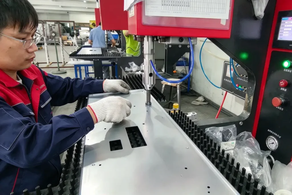
Self-clinching nuts, studs and standoffs need compatible sheet thickness, hardness, edge distance and installation access. Tapped holes and countersinks require enough material for the intended engagement.
Specify whether edges need deburring, deliberate rounding or another defined treatment. These requirements are different.
Surface Finish Selection
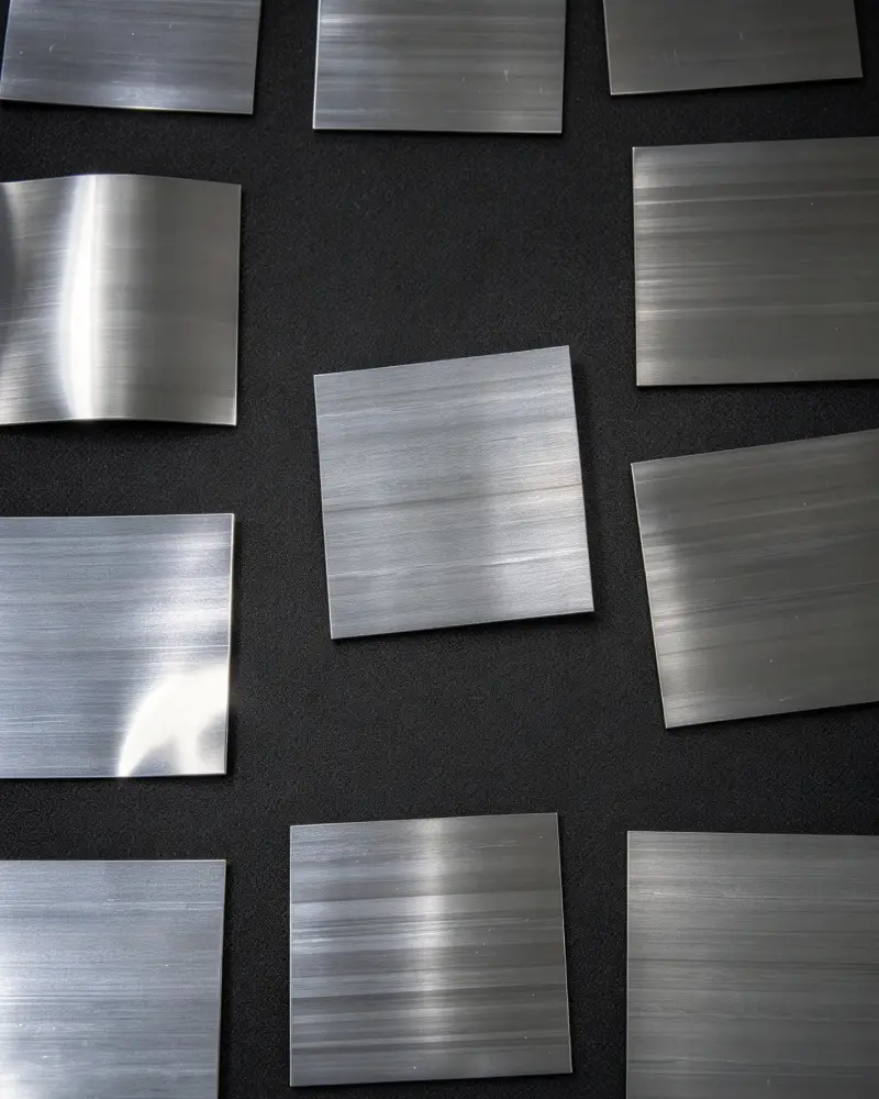
| Finish | Typical purpose | Detail affecting the finished part |
|---|---|---|
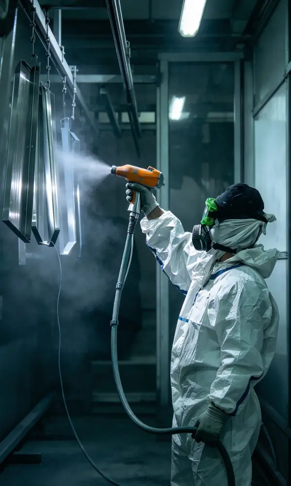
| Powder coating | Color and protective coverage | Buildup, masking and thread protection |
| Anodizing | Aluminum surface protection and appearance | Alloy-dependent appearance and dimensional change |
| Stainless steel passivation | Removal of free iron contamination | Cleaning requirements; not a substitute for a decorative finish |
| Zinc plating | Sacrificial protection for steel | Coating system, environment and fit |
| Nickel or tin plating | Application-specific surface or contact properties | Substrate preparation and functional requirements |
| Wet paint | Specified color and coating system | Preparation, film requirements and cure |
Confirm finish availability for the selected substrate and specification. Identify visible faces, grain direction, color references and protected contact areas.
Sheet Metal Part Details That Demonstrate Manufacturing Capability
ShincoMetal manufactures brackets, panels, enclosures and other sheet metal components from customer drawings. Laser cutting, press brake bending and hardware installation are handled in-house, while surface finishing is coordinated with external processing partners.
For formed brackets and panels, the manufacturing review connects the flat profile with the finished assembly requirements. Mounting holes, slots, bend positions and hardware locations must remain compatible through forming and finishing.
| Part requirement | Manufacturing consideration | Detail to examine |
|---|---|---|
| Mounting holes and slots | Review their relationship to bends, locating datums and mating components. | Hole geometry and access in the finished part. |
| Multiple bends and return flanges | Check the forming sequence, tooling clearance and finished envelope. | Flange arrangement, internal corners and assembly clearance. |
| Installed nuts, studs and standoffs | Confirm compatibility with sheet thickness, material hardness and installation access. | Hardware seating and clearance for mating fasteners. |
| Coated or cosmetic surfaces | Define visible faces, masking and protected interfaces before finishing. | Coverage, exposed edges and protected threads or contact areas. |
For a representative component, ShincoMetal can provide corresponding part photographs and a description of its actual manufacturing route, subject to confidentiality restrictions. The example should identify the material, important features and inspection basis so buyers can assess its relevance to their own drawings.
Inspection of Critical Features and Finished Parts
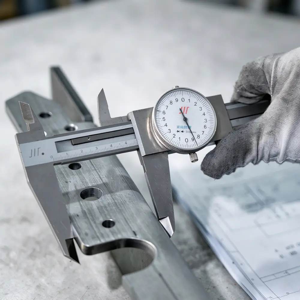
Inspection requirements should reflect how the component locates, fits and functions. Critical dimensions, formed geometry, joint requirements and visible surfaces need a defined acceptance basis rather than a general promise of precision.
ShincoMetal reviews drawing revisions and identified critical features before production, then selects inspection methods appropriate to the feature geometry and specified requirements.
| Inspection area | Inspection method and scope | Available documentation |
|---|---|---|
| Critical mating dimensions | Selected hole sizes, interface dimensions and feature relationships are checked against the specified drawing datums using suitable measuring equipment or gauges. | Feature-numbered dimensional records can be supplied when agreed in the quotation. |
| Formed geometry | Bend angles, flange dimensions and dimensions across bends are checked in the formed condition. Mating parts or agreed fixtures are used where assembly fit requires additional verification. | Formed-part measurement or fit-check records are available by agreement. |
| Welded structures | Inspection covers the agreed joint appearance, relevant dimensions and distortion. Leakage testing or other special testing must be separately specified and confirmed. | The applicable inspection records and acceptance criteria are agreed for the quoted welding scope. |
| Cosmetic surfaces | Designated visible faces are checked against agreed appearance references and viewing conditions. | Approved sample references or documented appearance criteria can form the acceptance basis. |
| Material and surface finish | Material identification and finishing documentation are checked against the purchase requirements. Coating measurements are included where specified and supported by the agreed process. | Material and finishing documents can be supplied within the scope confirmed at quotation. |
Inspection frequency, sampling, first-article approval and reporting requirements must be agreed before production. A dimensional report, material test report and certificate of conformity serve different purposes; specify which documents your project requires.
For coated parts, identify whether critical dimensions apply before or after finishing. Threads, contact areas, sealing faces and close-fitting interfaces may require masking or a separate acceptance check.
Include critical-feature markings, applicable standards and any customer-specific inspection requirements with your RFQ. This allows the quotation to account for the required measurement, documentation and approval scope.
Compare Quotes on the Same Scope
A meaningful quotation covers the same drawing revision, material grade, operations, finish, quantities and inspection requirements.
Prototype costs often include initial programming and setup. Repeat-order economics depend on material utilization, cycle time, tooling and release quantities. Dedicated tooling may reduce processing time, but its upfront cost needs sufficient volume to justify it.
Ask the quotation to distinguish:
- Part pricing and quantity breaks
- Dedicated tooling or nonrecurring charges
- Finishing and inspection scope
- Packaging and shipping terms
- Manufacturing completion and expected delivery timing
A larger order does not produce the same saving for every design. Compare the total purchasing scope, not only the quoted unit price.
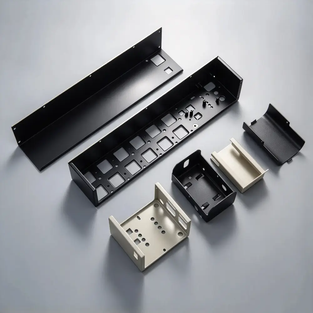
Compare the same drawing revision, finish and acceptance requirements. A lower unit price may cover a different manufacturing or delivery scope.
From Drawing Review to Delivery
01 Define the Part Package
Provide matching CAD and drawing revisions, material, finish, quantities and critical requirements. Identify unresolved details and acceptable alternatives.
02 Resolve Manufacturing Questions
The review should address bend access, feature spacing, joining, hardware and finishing sequence. Any proposed drawing changes need agreement before production.
03 Confirm the Quotation and Acceptance Scope
Align the revision, manufacturing scope, documentation, packaging and delivery requirements. Specify whether a sample or first-article approval is needed before a repeat batch.
04 Manufacture, Inspect and Pack
The agreed specification provides the basis for production and acceptance. Packaging requirements should account for cosmetic surfaces, protruding hardware and vulnerable flanges.
Lead time depends on material sourcing, tooling, process sequence, finishing and inspection. State your required receiving date and destination so manufacturing completion can be distinguished from arrival.
Frequently Asked Questions
What files should I send for a quote?
Send a STEP model and a PDF drawing showing the revision, material, finish and critical requirements. A DXF can help describe flat profiles. Keep file revisions aligned and identify which document governs if information differs.
Can I request prototype and production quantities together?
Yes. Include the initial quantity, expected repeat quantities and any release schedule. This supports comparison of validation costs and production economics. Minimum quantities and commercial terms are established for the specific scope.
How are cosmetic requirements specified?
Identify visible faces, grain direction, color or finish references, and the basis for acceptance. Include masking and protective handling requirements where finished interfaces or appearance are important.
How should I request a delivery date?
Provide the required receiving date, delivery destination and any sample-approval milestone. Timing must account for material, tooling, finishing, inspection and transport. Expedited requests require review of the complete route.
What tolerances apply to my part?
Achievable tolerances depend on material, thickness, size, geometry and process. Identify dimensions that control assembly, movement or sealing so they can be assessed in context. A tolerance suitable for a flat feature may not apply to a dimension across several bends.
Can you work from an assembly model?
Include the assembly model or relevant mating geometry with the part drawing. It can help explain interfaces and access requirements. The controlled part drawing should still define material, tolerances, finish and acceptance requirements.
What if my part needs louvers or custom formed features?
Provide the feature geometry and quantity with the main part files. Dedicated tooling, access and forming sequence need review before feasibility and tooling costs can be established.
Get a Quote for Your Sheet Metal Parts
Share your drawings or CAD files, along with material, quantity, finish, and delivery requirements. We’ll review your specifications and clarify any details needed to prepare your quote.
Factory Address
Building 1, No.8, Second Street, Huangjiang Town,
Dongguan City, Guangdong Province
Email
contact@shincometal.com
Phone / WhatsApp
+86 13392819510
Factory Visits
Please contact us in advance to arrange a factory visit.