
Custom Equipment & Audio Control Panels
Equipment panels bring connector access, mounting features and operating information into one part. Their design needs to work with the components behind the face while providing a clear, finished interface for the user. The examples shown here include a formed equipment panel and several compact audio control plates. Their openings, edge configurations and printed markings provide a reference for discussing similar custom fabrication projects.
Discuss a Similar Panel Project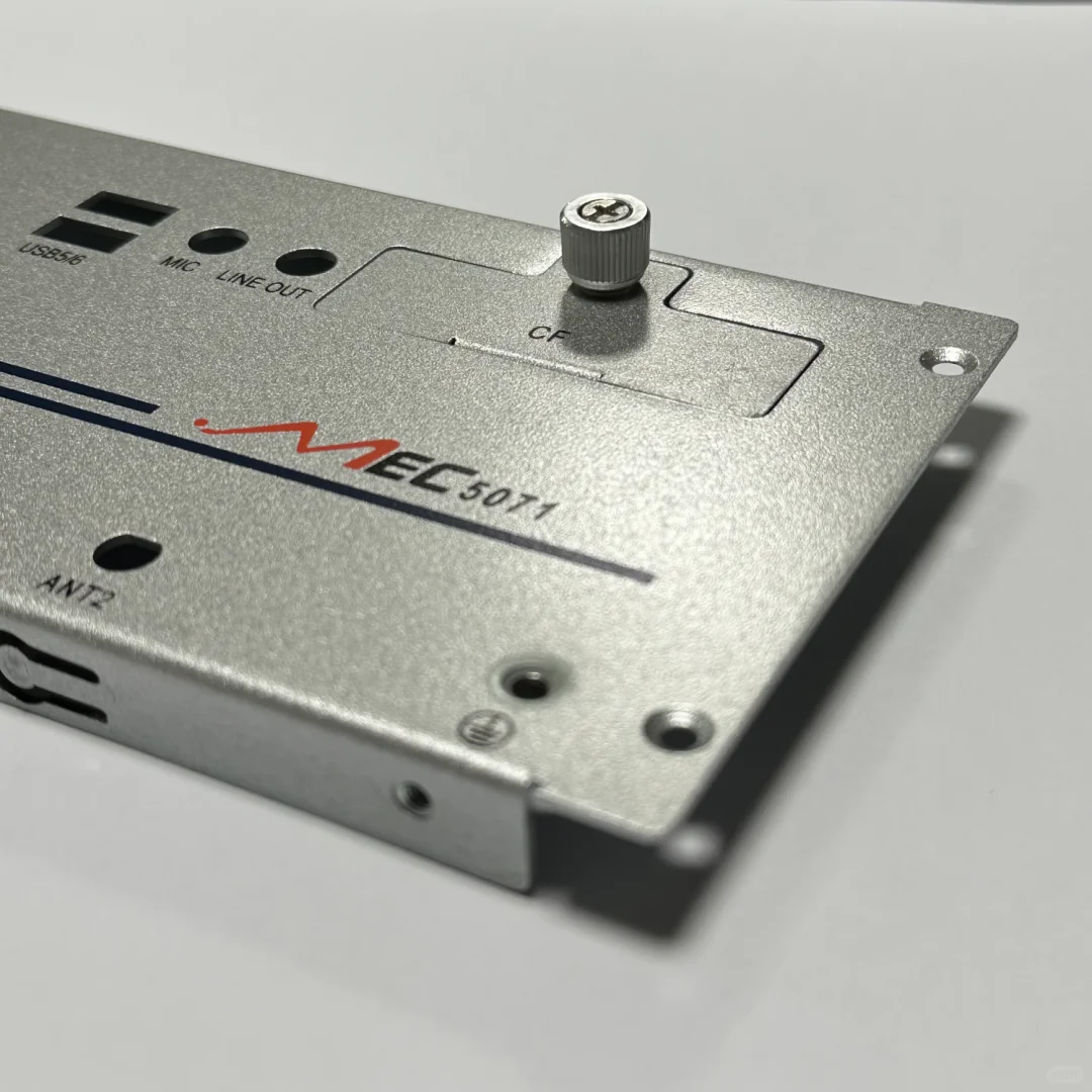
Fabricated Panel Examples
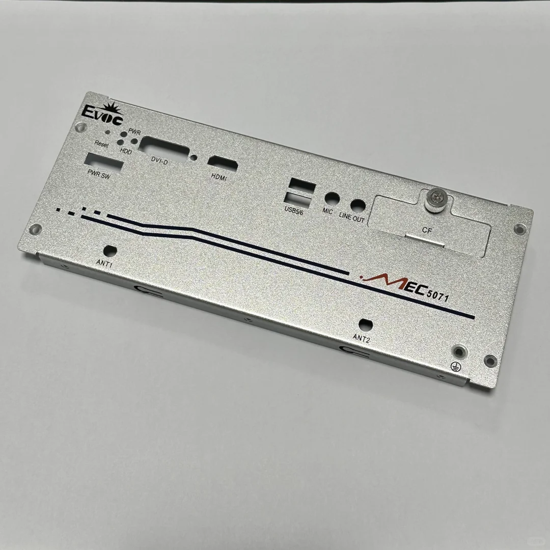
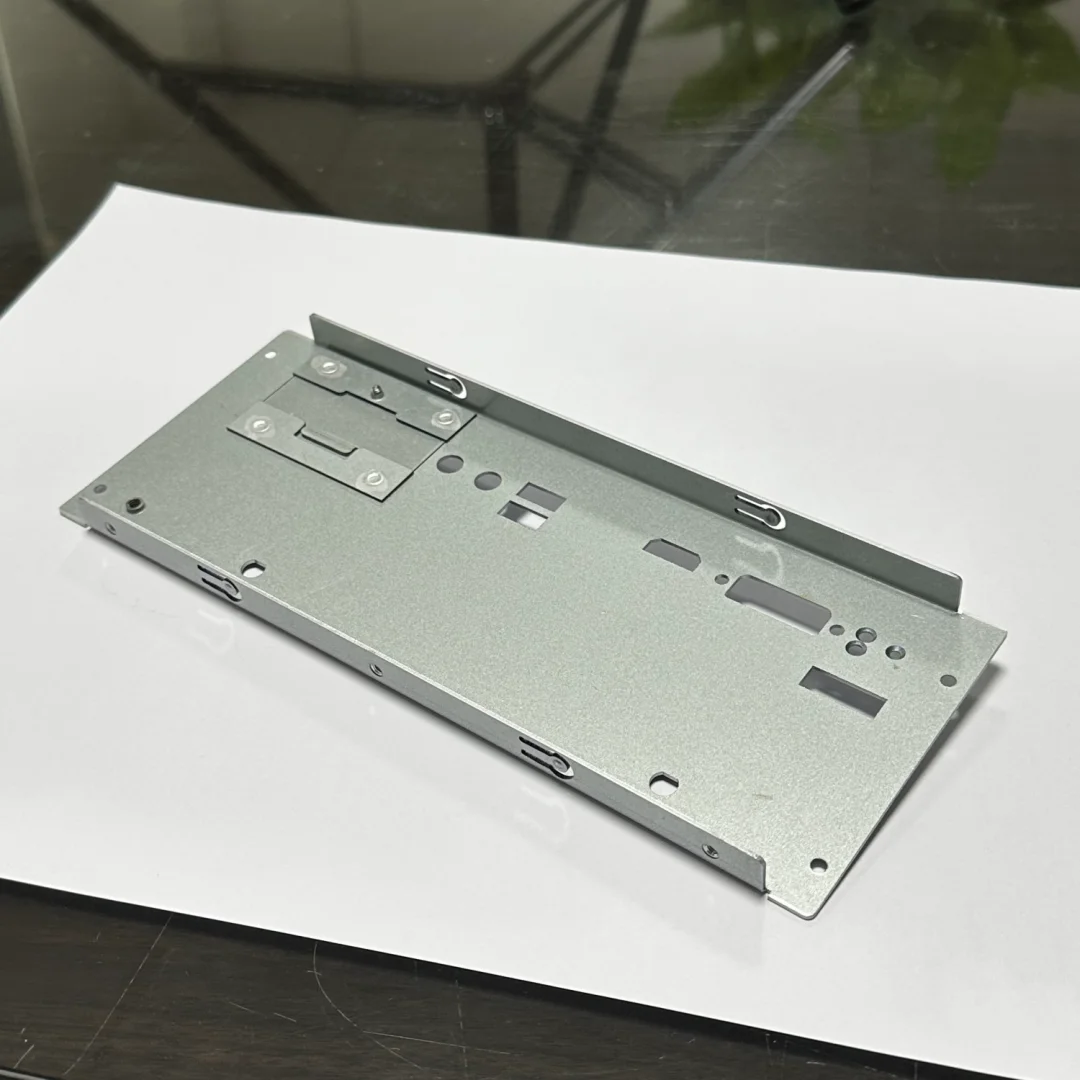
The long equipment panel combines several features on a single face: circular and shaped openings, mounting points, printed connector labels and formed returns. Its front and reverse views show how the visible interface relates to the surrounding metal structure.
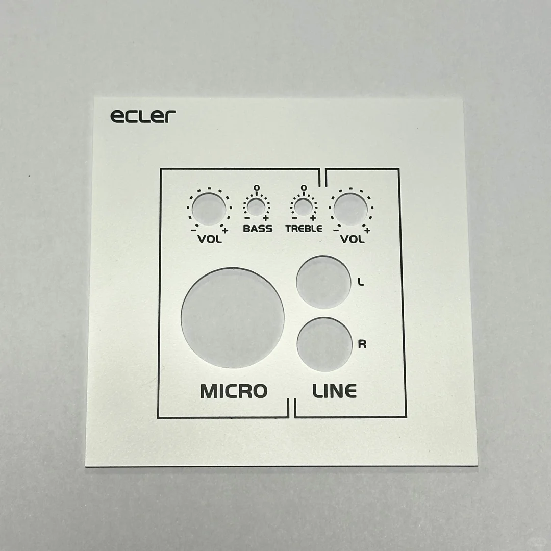
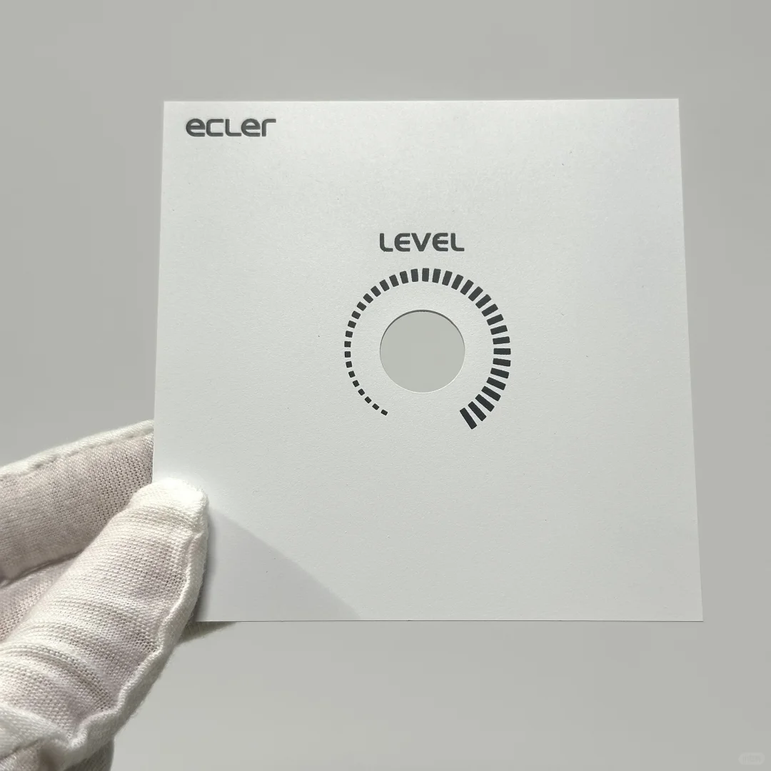
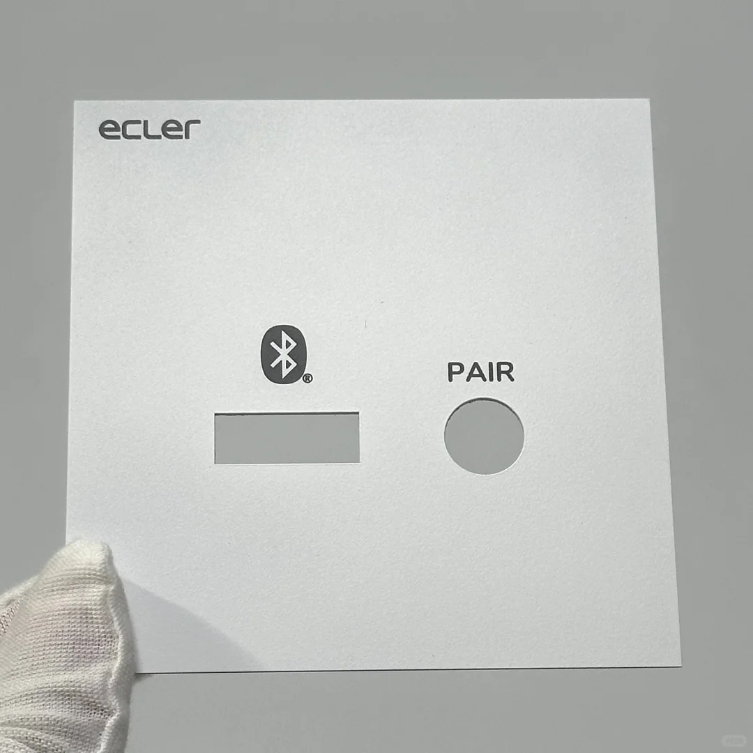
The compact plates use a different format. The MICRO / LINE plate groups multiple openings with operating labels, the LEVEL plate places a scale around a central opening, and the PAIR plate combines rectangular and circular openings.
These parts are presented together as fabrication examples. A similar project may use a different material, panel size, connector arrangement or graphic layout. For other panel formats and specification requirements, explore our custom sheet metal panels.
| Panel format | Visible features | Relevance to a similar project |
|---|---|---|
| Formed equipment panel | Multiple opening shapes, mounting features, printed legends and formed returns | Coordinating the front interface with enclosure mounting and space behind the panel |
| MICRO / LINE control plate | Several circular openings with grouped labels and control markings | Organizing controls and connectors within a compact interface |
| LEVEL control plate | Central opening with a surrounding printed scale | Positioning operating graphics relative to a control opening |
| PAIR interface plate | Rectangular opening, circular opening and printed label | Combining different component interfaces on one flat plate |
Mechanical Fit: Openings, Mounting and Formed Edges
An opening layout needs to account for the complete mating component. A connector may fit through the face but still need additional space for its body, cable connection, retaining hardware or installation tool.
For a formed panel, the relationship between the face and its returns also matters. Nearby bends can affect access and the available space behind the panel. The flat profile and formed condition should therefore be reviewed together. For related forming considerations, review our sheet metal bending services.
For a similar design, identify the features listed below. Material grade and thickness should be stated on the drawing. They affect stiffness, forming and the available manufacturing choices; they cannot be reliably determined from the finished photographs.
- Connector and control opening dimensions.
- Mounting-hole locations and their reference datums.
- Formed dimensions and bend directions.
- Clearance to components, fasteners and the enclosure.
- Edge requirements around handled areas and openings.
Manufacturing Approach
The existing fabrication scope identifies laser cutting, forming, sandblasting and silk-screen printing. Their application needs to follow the specification of each individual panel.
The useful manufacturing task is to connect these requirements. A formed return close to a connector opening needs sufficient installation clearance. A printed scale needs a defined position relative to the associated control. Surface preparation must also suit the specified graphic application.
For a new project, the drawings and finish specification should establish the required combination. The photographs provide a reference for the finished geometry and appearance, rather than a complete process specification.
| Process | Purpose | What needs to be defined |
|---|---|---|
| Laser cutting | Produces the flat outline and component or mounting openings | Material, thickness, opening geometry and critical dimensions |
| Forming | Creates returns and other specified formed features | Bend direction, formed dimensions and mating clearances |
| Sandblasting | Produces a textured surface where specified | Material, visible areas, required surface character and subsequent finishing requirements |
| Silk-screen printing | Applies labels, symbols and operating scales | Artwork, colors, orientation and registration references |
Printed Graphics and Surface Appearance
The pictured panels show how labels and scales can be arranged around mechanical openings. On the long panel, the legends identify individual interfaces. On the compact plates, the graphics group controls and communicate their functions.
For a similar panel, the mechanical drawing and artwork should use matching references. This helps avoid a correctly printed graphic being placed in the wrong relationship to an opening.
Artwork instructions should identify the items below. A photograph can show layout and appearance. Requirements for adhesion, abrasion resistance or other graphic performance need separate specifications and, where necessary, agreed testing. Review our surface finishing requirements when defining appearance, masking and finished-part requirements.
- Text, symbols and scales.
- Required colors.
- Installed reading orientation.
- Graphic position relative to mechanical features.
- Visible faces and areas that must remain free of markings.
Inspection Requirements for a Similar Panel
Inspection should follow the features that control fit, function and appearance. The following checks provide a starting point for agreeing project requirements.
Where assembly fit is critical, provide the mating-component dimensions or an agreed fit-check reference. Where a functional finish or graphic test is required, define its method and acceptance criteria before production.
The finished-part photographs illustrate geometry and appearance; they do not establish measured conformity or replace inspection records.
| Feature | Inspection focus | Acceptance reference |
|---|---|---|
| Material and thickness | Confirm the specified material and sheet thickness | Drawing, purchase specification and any agreed material documentation |
| Openings and mounting holes | Size, location and relationship to datums | Approved mechanical drawing |
| Formed features | Return position, formed dimensions and relevant clearances | Formed-part drawing and mating references |
| Edges | Burrs and specified edge condition | Drawing notes or agreed workmanship criteria |
| Printed graphics | Content, orientation and position relative to openings | Approved artwork and registration requirements |
| Visible finish | Surface consistency and handling damage | Finish specification or approved reference sample |
Finished Details and Design Variations
The front and reverse views of the long panel show how a visible interface can be combined with formed edges. The compact plates demonstrate how the same basic task—positioning openings and operating information—can be adapted to different control layouts.
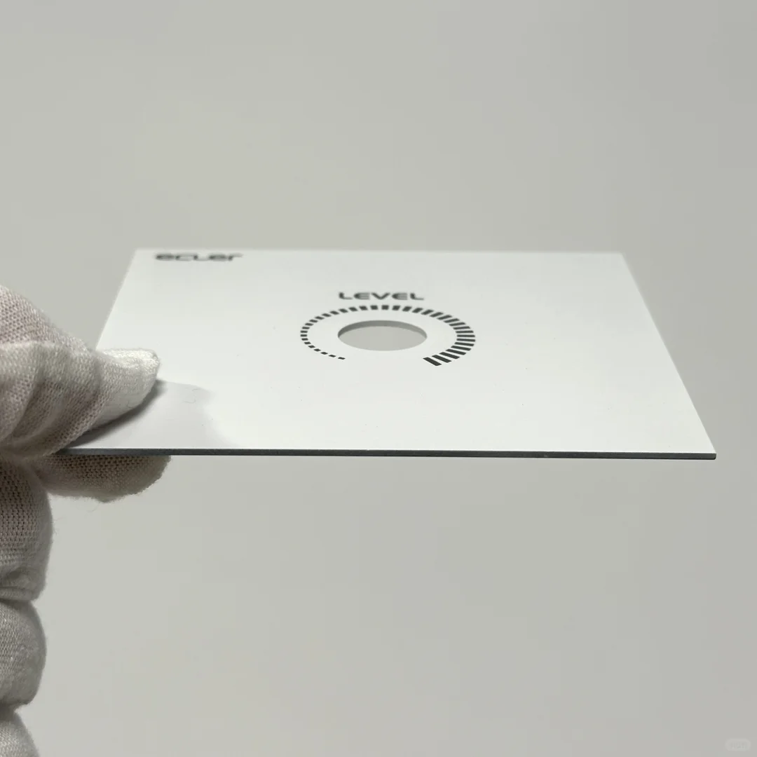
The PAIR plate combines two opening shapes on one face. The oblique LEVEL view shows the plate’s edge and flat profile. These details help communicate the intended panel format when discussing a related design.
Your project does not need to reproduce these examples. A different connector pattern, mounting arrangement, surface specification or graphic layout can be submitted for review.
Frequently Asked Questions
What information should I provide for a similar panel?
Send a dimensioned drawing or model, quantity, material grade, thickness, finish requirements and artwork. Include mating-component drawings or dimensional references where connector or mounting fit is important.
Can my panel use a different opening layout?
Yes. Submit the required connector and control arrangement, mounting features and available space. The examples show reference formats rather than a fixed specification.
How should I specify critical dimensions?
Identify the features that control installation, including opening sizes, hole positions and formed dimensions. State the required tolerances and datum references on the drawing.
How should I supply printed artwork?
Provide separate artwork with revision references that match the mechanical drawing. Identify colors, text orientation, visible faces and how the graphics are positioned relative to the openings.
What if the material or finish is not yet decided?
Describe the operating environment, appearance requirements and mating arrangement in your inquiry. Identify undecided items so they can be discussed during the fabrication review.
Do the photographs establish material or performance specifications?
No. They show the parts’ visible features. Material grade, thickness, dimensional acceptance and any functional finish requirements need to be defined separately.
Request a Quote for Your Equipment or Audio Panel
Send your panel drawings and artwork to ShincoMetal for a fabrication review. Include the material and thickness, overall dimensions, connector openings, mounting arrangement, finish, printing requirements and quantity. Highlight critical fit requirements and any first-article or inspection documentation needed. If some details remain undecided, identify them in your inquiry so they can be reviewed alongside the proposed design.
Factory AddressBuilding 1, No.8, Second Street, Huangjiang Town, Dongguan City, Guangdong Province
Emailcontact@shincometal.com
Phone / WhatsApp+86 13392819510
Factory VisitsPlease contact us in advance to arrange a factory visit.