
Sheet metal bend radius usually refers to the inside radius of a formed bend. Choose it using the alloy, temper, thickness, grain direction, and forming method. Then confirm that available tooling can produce the radius and that the finished corner fits the assembly. A 1T radius is not a universal minimum.
The checklist below identifies the data needed to select a radius; it does not specify universal material minimums or ShincoMetal capability limits. The tooling discussion focuses on press-brake air bending unless another method is identified.
What Is Bend Radius in Sheet Metal?
Inside bend radius is the radius of the inner curved surface of a formed sheet metal corner. A smaller radius creates a tighter corner; a larger radius creates a wider curve.
Your choice affects cracking, assembly clearance, and manufacturing cost.
Inside Radius vs. Outside Radius
Most sheet metal drawings specify the inside bend radius—the radius of the curve inside the corner.
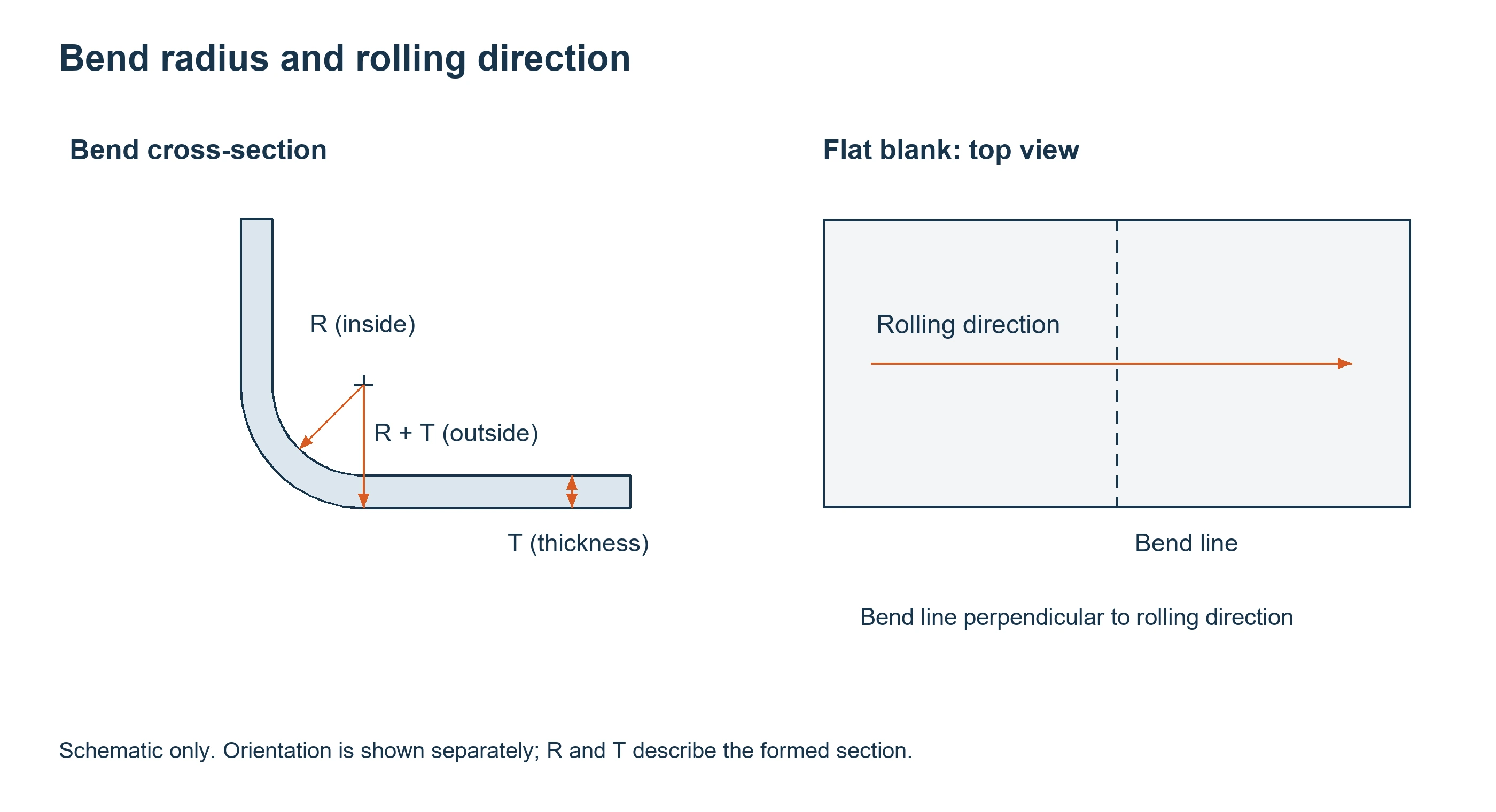
The outside radius includes the material thickness:
Outside radius = Inside radius + Sheet thickness
For example, a 2 mm thick sheet with a 2 mm inside radius has a 4 mm outside radius. Check both when your part must fit around another component.
The section sketch below shows inside radius R, thickness T, and outside radius R + T. A separate blank-view sketch identifies the bend line and rolling direction; the two views are schematic and not to scale.
Charts often express inside radius as a multiple of thickness, or T:
- 1T: Radius equals sheet thickness.
- 2T: Radius equals twice the thickness.
R/T expresses the same relationship as a ratio. A 4 mm inside radius in 2 mm sheet has an R/T of 2.
Minimum Radius vs. Practical Production Radius
The minimum bend radius is the smallest inside radius a material can handle under specified forming conditions without cracking or unacceptable damage.
A practical production radius may be larger to accommodate material variation and suit available tooling.
Avoid specifying the material minimum unless the geometry requires it. A suitable radius can reduce cracking risk and may reduce tooling costs, provided the resulting corner still meets assembly-clearance requirements.
Sheet Metal Bend Radius: Material and Tooling Checks
Choose a radius using forming data for the actual stock and a check of the intended tooling. A radius offered for one material thickness on one machine is not a universal material minimum.
| Material on the drawing | Data to confirm before choosing an inside radius | Production check |
|---|---|---|
| Cold-rolled steel | Exact grade, thickness, and supplied condition | Confirm that the selected tooling can achieve the specified radius and angle. |
| 304 stainless steel | Grade, thickness, and supplied temper or condition; a 2B finish alone does not define forming behavior | Check springback and the released dimensions with the intended setup. |
| 5052-H32 aluminum | Alloy, H32 temper, thickness, and bend orientation | Use matching forming data and inspect a representative bend if the setup is unproven. |
| 6061-T6 aluminum | Alloy, T6 temper, thickness, and bend orientation | Do not reuse a radius qualified for another aluminum alloy or temper without checking it. |
| C110 copper or C260 brass | Exact alloy, temper, thickness, and bend orientation | Obtain temper-specific forming data rather than using a generic copper or brass radius. |
For conventional air bending, WILA's V-opening guide explains how changing the die opening affects the formed radius, bending force, minimum leg length, and flat pattern. This tooling guidance helps evaluate a setup; it does not supply alloy- and temper-specific minimum bend radii.
If an alloy substitution is proposed, obtain design approval and recheck strength, radius, corner clearance, and nearby mounting features. Keep material formability data separate from the machine's available tooling options.
How Do You Determine the Minimum Bend Radius?
Determine minimum bend radius from forming data that matches the material grade, temper, thickness, bend orientation, angle, and forming method. Then confirm that the intended setup can form the part without unacceptable cracking or damage. A fabricator's available radius is a tooling option; it does not establish the material's minimum.
If matching data is unavailable or the design approaches the forming limit, qualify the setup with a representative test bend. Record the conditions and the acceptance criteria rather than treating a successful result as a rule for all stock.
How to Choose the Right Bend Radius
The following design example uses a 2 mm thick 5052-H32 L-bracket with one 90-degree bend and a mounting hole on each flange. Its dimensions and bend data are illustrative, separate from the published shop-floor report below.
Which Material, Thickness, and Grain Direction Apply?
Start with the full material specification. “Aluminum, 2 mm” leaves out details that affect cracking risk.
For our bracket, confirm:
- Alloy and temper: 5052-H32.
- Thickness: Nominal 2 mm, including the expected supply tolerance.
- Grain direction: Place the bend line perpendicular to the rolling direction where practical. See grain-direction guidance. The article includes heavy-plate examples; its numerical radius recommendations should not be transferred directly to this 2 mm bracket.
Check the blank before approving the bend:
- Angle: Specify the finished angle clearly. For this bracket, the bend angle and included angle are both 90 degrees.
- Burrs: Remove burrs and inspect cut edges where they cross the bend.
- Surface damage: Check for deep scratches, especially on the surface that will stretch around the outside corner.
Can Available Tooling Produce the Radius?
In air bending, the V-die opening—the gap between the die shoulders—helps determine the inside radius, forming force, and flange support. A wider opening generally produces a larger radius but needs more flange length. Check the available support before selecting the setup. WILA’s air-bending guidance and short-flange guidance explain these trade-offs.
Air bending supports the sheet at the die shoulders while the punch controls penetration; the sheet does not fully conform to the die. Bottoming brings the sheet into fuller contact with the tooling, while coining uses higher pressure to plastically set the bend. Do not transfer an air-bending radius rule or setup directly to these other methods.
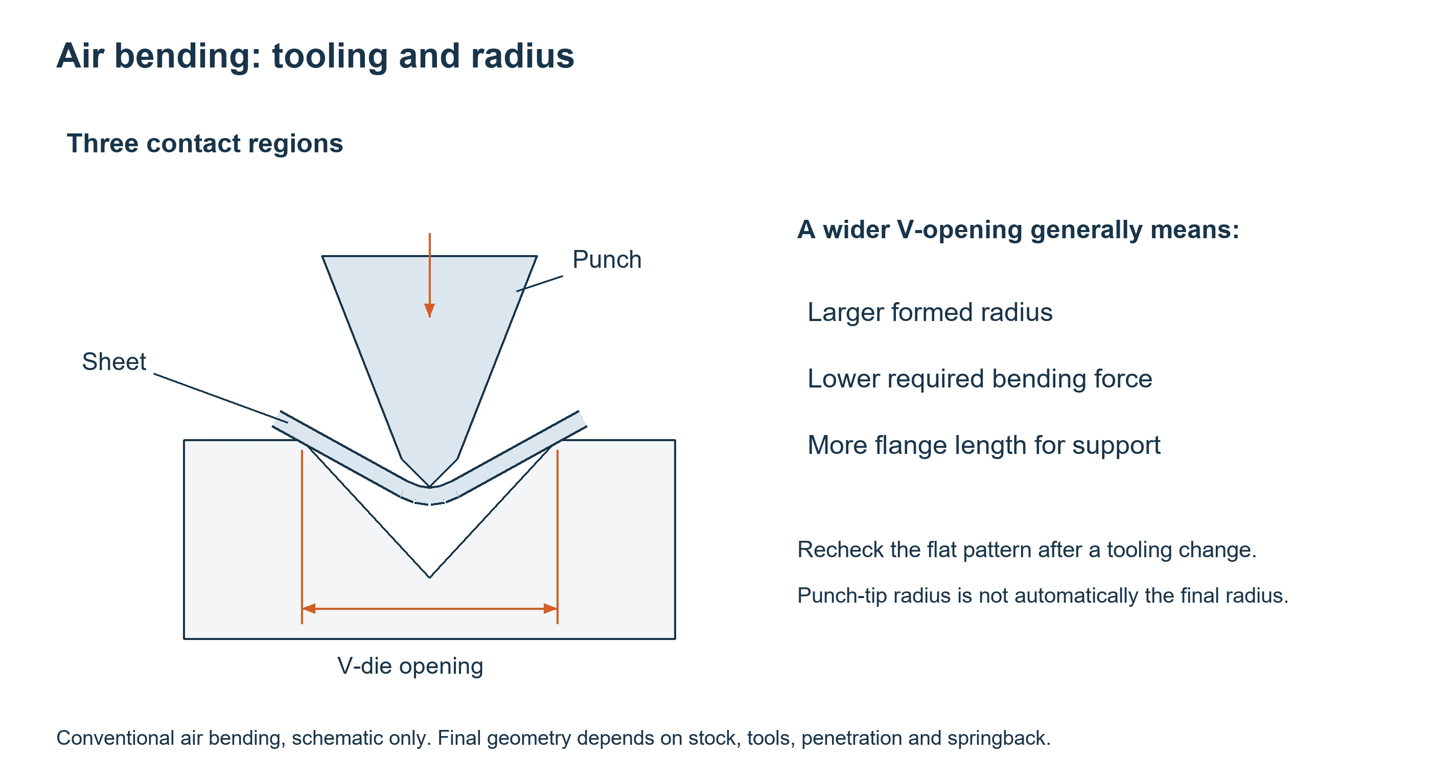
Conventional air bending, schematic only. The die opening affects radius, forming force, and flange support.
The punch radius matters, too. But its tip radius does not necessarily match the finished inside radius. WILA’s tooling guide explains how the punch tip and die opening affect air bending; confirm the resulting radius for the actual material and tool combination.
After the tool releases, springback usually opens the bend slightly and may increase the radius. The shop may need to adjust its forming settings and verify the released part against the specified angle and dimensions.
Suppose your fabricator confirms that its standard setup can produce a 3 mm inside radius in our bracket. That becomes the candidate radius, subject to material and fit checks. It isn’t a general minimum for all 2 mm aluminum.
Will the Finished Corner Fit the Assembly?
With a candidate 3 mm inside radius in the bracket model, check whether:
- The curved corner clears the mating part.
- Each flange is long enough for the selected die.
- The mounting holes stay clear of the bend zone.
- The finished hole positions meet the assembly requirements.
For holes and slots near the corner, define clearance from the feature edge to the bend tangent on the drawing. Ask the fabricator to check the actual opening and bend zone; there is no single clearance multiplier established by this example. At intersecting bends, review relief geometry to avoid tearing or interference.
At nominal thickness, the bracket’s outside radius would be 3 + 2 = 5 mm. That outer curve may matter if the bracket sits inside a housing.
Where space allows, agree on a production margin above the confirmed material minimum. Use the test-bend and inspection checks below when fit is critical or the setup is unproven.
Design Review Example: Which Dimension Actually Needs Control?
Consider two uses for the illustrative 2 mm bracket. In the first, it mounts two flat faces and neither mating part touches the curved corner. In the second, the bracket wraps around a housing whose corner occupies that space. The same proposed radius change needs a different decision in each assembly.
For the flat-face mounting arrangement, ask whether the drawing's radius tolerance protects a function or simply repeats a CAD default. If the corner is clear, discuss a radius compatible with the shop's existing tooling while retaining the required hole positions, flange dimensions, and angle. Approve the revised drawing and flat pattern before cutting; a non-contacting corner does not make the dimensions independent of the radius.
For the wraparound arrangement, compare the formed corner with the housing profile and its tolerance envelope before accepting a larger radius. A setup that bends the stock successfully can still produce an unusable assembly. If the available tooling cannot satisfy both formability and clearance, discuss a corner relief, revised mating geometry, or a separately joined construction, then check the resulting strength and assembly requirements.
The useful review question is: what fails if this radius changes? Use the answer to decide whether to control the radius closely or give the fabricator room to propose a producible corner. These are hypothetical design situations, not customer project records.
Published Shop-Floor Report: A Larger Die Did Not Produce the Expected Radius
A reader report in Steve Benson’s air-formed radius report, published in 2018 and updated in 2023, shows why a die-opening estimate needs a measured check. This is an external report, not a ShincoMetal production result.
The reader described air bending 0.125 in. (3.18 mm) 5052-H32 aluminum with a 1 mm punch and a 16 mm die opening. The achieved radius did not match the estimate. To obtain a larger radius, the shop switched to a 50 mm die opening and expected about 0.295 in. (7.49 mm). Instead, the reported inside radius was 0.109 in. (2.77 mm).
Benson discussed material strength, punch geometry, and the limitations of die-opening rules. The useful result is the reported measurement after the tooling change: increasing the die opening did not produce the radius the shop expected. The report does not give the initial measured radius, bend angle, grain orientation, inspection method, or a later successful correction; it is not a complete process-qualification record.
For your own trial, record both tooling configurations and the measured released radius, angle, and cracking condition. Keep predicted values separate from measurements, and use the result to review the setup and flat pattern.
How Bend Radius Affects Your Flat Pattern
Your flat pattern is the sheet’s shape before bending. Change the bend radius, and you may need to change the blank size to keep the finished dimensions correct.
Bend Radius, K-Factor, and Bend Allowance
During bending, the outer surface stretches and the inner surface compresses. Between them sits the neutral axis, where the length stays roughly unchanged.
The K-factor describes that axis’s position through the thickness. Bend allowance is the length along the neutral axis through the curved section. Onshape’s sheet metal guide defines both terms and explains the difference between K-factor, bend allowance, and bend deduction as CAD calculation options.
Use this formula:
Bend allowance = (π ÷ 180) × θ × (R + K × T)
Where:
- θ: Bend angle in degrees, measured from flat.
- R: Inside bend radius.
- K: K-factor.
- T: Sheet thickness.
Take our 2 mm bracket with a 3 mm inside radius and a 90-degree bend. Using an illustrative K-factor of 0.40 gives a bend allowance of about 5.97 mm.
That’s the developed length of the curved section—not extra material to add blindly to the finished flange dimensions.
How Do You Calculate the Flat Length from Outside Flange Dimensions?
For a single 90-degree bend, bend deduction converts outside flange dimensions into a flat length. Here, each outside flange dimension runs from its free edge to the theoretical sharp intersection of the extended outside faces—not to a bend tangent.
Use the same illustrative bracket, and assume outside flange dimensions A = 30 mm and B = 40 mm. The geometry and calculations are:
- Outside setback, SB = (R + T) × tan(θ/2) = (3 + 2) × tan(45°) = 5.00 mm.
- Bend allowance, BA = (π/180) × 90 × (3 + 0.40 × 2) = 5.97 mm.
- Bend deduction, BD = 2 × SB − BA = 10 − 5.97 = 4.03 mm.
- Flat length, L = A + B − BD = 30 + 40 − 4.03 = 65.97 mm.
In these expressions, R is inside radius, T is thickness, θ is bend angle measured from flat, and K = 0.40 is the illustrative neutral-axis factor used in BA. SB is the distance from the outside theoretical corner to each tangent, BA is the neutral-axis arc length, BD is bend deduction, and L is total developed length across the bend. All linear dimensions are in millimeters.
The straight tangent lengths provide a cross-check: (30 − 5) + (40 − 5) + 5.97 = 65.97 mm. These equations describe the idealized single-bend geometry; production accuracy still depends on calibrated bend data. Do not apply this outside-dimension deduction to flange lengths measured to the tangents, and do not treat K = 0.40 as a validated value for 5052-H32.
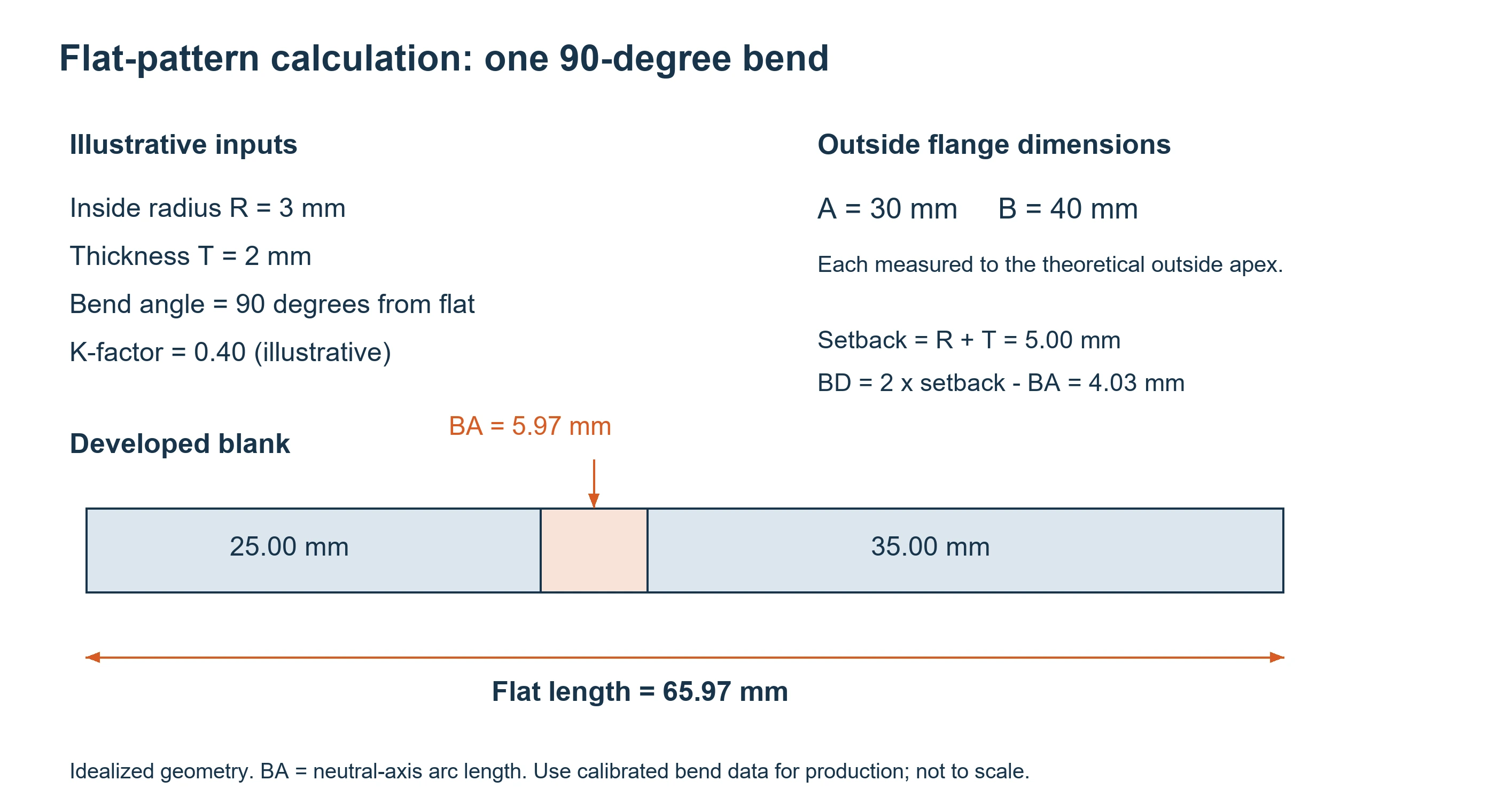
Illustrative 90-degree example: R = 3 mm, T = 2 mm, K = 0.40. Use calibrated bend data for production.
Use the Fabricator’s Bend Data in CAD
Use the fabricator’s tested bend table or calibrated K-factor for the material and tooling. A CAD default may unfold the model without producing the correct blank size. For example, Onshape’s documentation lists a default bend K-factor of 0.45; that software default is not a validated value for every alloy, thickness, or forming setup, and it is separate from the illustrative K = 0.40 used above.
For a first-off dimensional error, separate the checks instead of changing the K-factor immediately:
- Wrong angle: Verify the released angle and the dimension's inspection setup first. A bracket held against a square can conceal an angle error that appears when it is released.
- Correct angle, wrong dimension: Check the blank length, bend location, actual radius, and drawing datum. Compare the measured part with the CAD model using the same dimension convention before revising bend allowance or deduction.
- Fits only when forced: Check hole alignment and corner clearance in the free state. Decide whether clamping is an intended assembly condition or is masking a mismatch.
This diagnostic order is a proposed review method, not a report of a completed shop trial. Change a setting only after the measurements identify the discrepancy, then verify a new first-off part.
Confirm who controls the production flat pattern, too. If the shop changes the radius or forming setup, it should review the bend data and verify that the revised flat pattern can meet your required finished dimensions. Any necessary design changes should be agreed before production.
Check Your Bend Before Production
What to Specify on Your Drawing
Specify the following so the fabricator can make and inspect the part:
- Material: Exact grade, temper or condition, and thickness.
- Finished inside radius: Identify critical radii and any tolerance they need.
- Final bend angle: State the required angle after springback.
- Key dimensions: Hole locations, flange dimensions, and assembly clearances.
- Grain direction: Specify it where forming performance depends on orientation.
- Surface requirements: Mark cosmetic faces and areas where tool marks matter.
For the bracket, prioritize the mounting-hole positions and corner clearance. Approve any proposed radius change before production.
When to Run a Test Bend
Request a test bend when the radius is near the material’s limit, the setup is unproven, or assembly fit is critical.
Use a sample that matches production:
- Same alloy, temper, and thickness.
- Same rolling direction relative to the bend line.
- Same cutting and edge preparation.
- Same machine, punch, die, and forming method.
A simple strip can help confirm bend behavior. For closely spaced bends or tight clearances, test the actual part geometry as well.
For a part with several bends, check the forming sequence as well as material behavior. A successful strip test does not establish that a partly formed component will clear the punch, die, or backgauge during later bends. Review the complete part geometry before approving production.
Record the setup and results to support repeat production, and recheck them when material or tooling conditions change.
How to Check the Finished Radius and Angle
Inspect after the forming force is removed. The shape under the punch isn’t the final shape.
Check four things:
- Radius: Use a radius gauge for a quick check. Use optical or profile measurement when the tolerance needs it.
- Angle: Measure with a suitable angle gauge or protractor.
- Damage: Inspect the outer bend surface and edges for cracks or tearing.
- Fit: Place the part against its mating component or an inspection fixture.
Inspect functional dimensions from the drawing datums. Where a mating component or an agreed fixture is available, check hole alignment and corner clearance. Distinguish free-state inspection from clamped inspection: forcing a bracket into position can hide a fit problem.
Frequently Asked Questions
Does Punch Radius Equal the Finished Inside Bend Radius?
Punch radius does not necessarily equal the finished inside bend radius in air bending. The V-opening, material behavior, punch geometry, and springback affect the released shape. Confirm the achievable radius with the fabricator instead of copying the punch-tip value into the drawing.
Does Changing Bend Radius Affect the Flat Pattern?
Changing bend radius can change bend allowance and the developed blank length needed to hold finished dimensions. Update the CAD bend data and check the dimension convention before releasing a revised flat pattern.
Is a 1T Bend Radius Always Safe?
No. 1T means the inside radius equals the sheet thickness, but it isn’t a universal minimum.
It can be a useful starting point for some ductile materials. Harder alloys or tempers may need more room. Check material-specific data, grain direction, and tooling before using it.
Is 0.030 Inch a Universal Bend Radius?
No. 0.030 inch is 0.762 mm, approximately 0.76 mm when rounded to the nearest 0.01 mm. That dimension alone does not establish suitability for a material, thickness, or tooling setup.
Ask your fabricator which radii work with its tooling and your exact stock. A shop’s preferred radius shouldn’t replace a material check.
Can You Bend 6061-T6 Aluminum Without Cracking?
6061-T6 can be bent without cracking under suitable material and forming conditions, but a specified radius alone does not guarantee a crack-free result. It is generally less forgiving of tight bends than 5052-H32.
Use thickness-specific recommendations, place the bend line perpendicular to rolling where practical, and test the intended setup. If the corner must be tight, consider whether 5052-H32 meets your strength needs.
What If Your Design Needs a Tighter Radius?
First, check whether the tight corner is essential. A small clearance change may let you use a larger radius.
If it is essential, discuss:
- A more formable alloy or temper.
- Different tooling or a qualified forming process.
- A revised part geometry or separate joined pieces.
Don’t assume a sharper punch will solve it. Material limits still apply.
Prepare Your Drawing for Bend Review
When discussing a bent part with ShincoMetal, provide the drawing or CAD model, material grade and temper, thickness, quantity, finish, intended radius, flange lengths, and critical assembly dimensions. Ask the fabricator to confirm the proposed radius and identify any geometry changes before production.
Sources
These references support the tooling discussion, grain-direction guidance, CAD definitions, and separately attributed external report used above.
- WILA: V-opening — effects of die opening on radius, force, minimum leg length, and flat pattern; tooling-manufacturer guidance, not a material minimum-radius table.
- WILA: Air Bending — V-opening, punch-tip radius, forming force, and minimum flange considerations.
- WILA: Bending Short Flanges — flange support and the effect of changing the V-opening on radius and flat pattern.
- Onshape: Sheet Metal Model — K-factor, bend allowance, and bend deduction definitions.
- THE FABRICATOR: The Fundamentals of Heavy Bending — grain orientation and forming considerations; heavy-plate numerical recommendations are not applied to the bracket example.
- Steve Benson, THE FABRICATOR: Predicting an Air-Formed Sheet Metal Inside Bend Radius — published November 19, 2018; updated October 25, 2023. Reader-reported 5052-H32 tooling change and measured radius, not a ShincoMetal trial.